LED Display Controller
Team Menber
Sheng-Jung Yu and Zih-Sing Fu
Report Link
Abstract
We implemented a LED display controller which receives multiple gray-level images in Verilog. Each image consists of 32*16 pixels and the pixels size is 16 bits. According to the value of each pixel, the display outputs Pulse Width Modulation (PWM) signals to control the brightness of LEDs. Specifically, the duty cycle of a signal equals to the ratio of the pixel value to 65536 (216). We then synthesis the implementations into chip layout by Design Compiler and Innovus.
Design Specification
The LED display controller processes a scanline, which is a row of pixels, at a time. When the signal Vsync is set to high, the controller starts to output signals for a scanline according to the pixel values. The LED display controller supports two mode: 30FPS mode and 60FPS mode. Two SRAM are integrated into the designs.
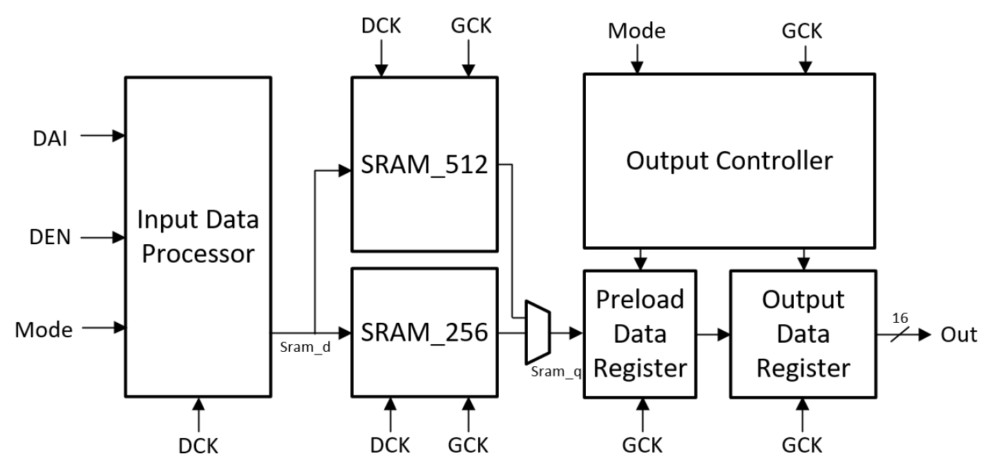
Block Diagram
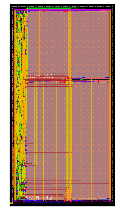
Layout